
 Product
 Brand
Brand
 Articles
 Tools
Tools
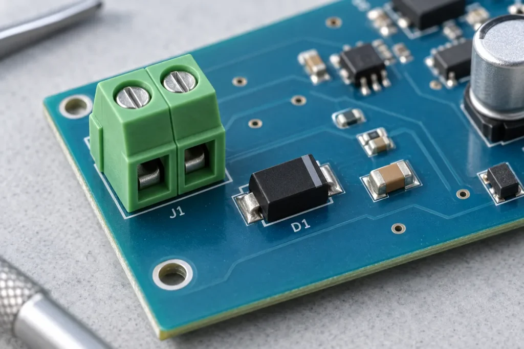
*This is a reference circuit description based on the conventional connector-level clamping arrangement described in the general application guidance that protection component manufacturers publish. It is not a manufacturer’s official reference design and it is not a tested build. Confirm ratings against the datasheet for the exact protection device and against the standard that applies to your product.*
The circuit. At the point where the supply or signal enters the board: a transient voltage suppressor from the line to the return, a series element between the connector side and the protected circuitry, and a second, faster clamp or a filter at the device pin where the line is sensitive. The return for the first clamp is the connector’s own return, taken at the connector, not signal ground somewhere else on the board.
The three voltages that must be ordered correctly. The maximum normal operating voltage of the line, including tolerance, ripple and any legitimate transient the supply produces. The standoff voltage of the TVS, which must sit above that maximum so the device does not conduct in normal operation and does not leak appreciably. And the clamping voltage at the peak pulse current the standard specifies, which must sit below the absolute maximum of everything the line feeds. Infringing any of the three in either direction produces a design that either leaks in normal operation or does not protect.
The peak pulse rating is a waveform, not a number. A TVS’s peak pulse power rating is quoted for a specific waveform, and the same device has very different capability for a fast ESD event than for a slower surge. The rectifier-style derating curve in the datasheet converts the rating to the pulse duration you actually expect. Comparing a rating to a requirement without matching the waveform is the most common way a protection design is nominally compliant and practically ineffective.
Why the series element matters. With no impedance between the connector and the protected device, the clamp must hold the line below the device’s absolute maximum at the full surge current, which forces a large device. A series resistor or a ferrite reduces the current the second stage sees and shares the energy between the two clamps. The series element must then survive the current the first clamp diverts — a point that is easy to overlook, because the resistor’s steady-state rating says nothing about a microsecond pulse.
Capacitance, if the line carries data. A TVS presents capacitance, and on a data line that capacitance loads the signal and slows its edges. Protection for high-speed lines is chosen from parts specified for that purpose, and the capacitance budget is part of the signal integrity budget. On a power input this constraint does not apply, which is why the same protection strategy is not transferable between a supply line and a data line.
Layout, at the connector. The clamp goes at the connector, before the trace that leads into the board, with a short and wide return to the connector’s ground. A clamp placed after a via and a length of trace leaves that inductance in series, and the inductive overshoot at the device pin can exceed the clamping voltage the datasheet promises. The second stage goes at the pin it protects, for the same reason.
What to verify. Standoff voltage above the maximum normal line voltage with margin. Clamping voltage at the applicable pulse current below the protected device’s absolute maximum. Peak pulse rating matched to the waveform, not to a headline figure. Series element pulse capability. Capacitance against the signal budget if the line carries data. Return path at the connector, measured rather than assumed. And the applicable standard for your product, because the required test levels are a product-level requirement and not a component property.
This reference circuit describes a conventional protection arrangement and the relationships between its ratings. It is not a manufacturer’s reference design and has not been built or tested as part of this article. Confirm the applicable standard levels and every rating against the datasheets for the exact components you select.
Selecting protection for an input?
Send the part numbers and quantities through our RFQ form, or contact us and we will confirm availability and lead time. Our catalogue lists circuit protection parts by category.